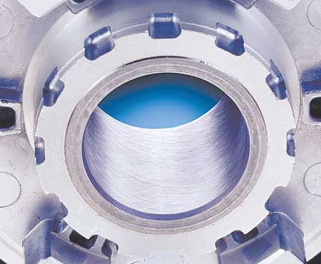
The crosshatch surface finish left in the bore by honing enhances oil retention to lubricate and seal sliding/mating parts such as pistons, plungers and shafts.
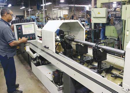
Gun and cannon barrels are often honed after reaming to improve roundness, bore size, geometry and surface finish. Reaming marks can be re-moved and the surface smoothed to reduce fouling and enhance cleanability of the bore. Photo shows a barrel blank for a .50 cal machine gun.
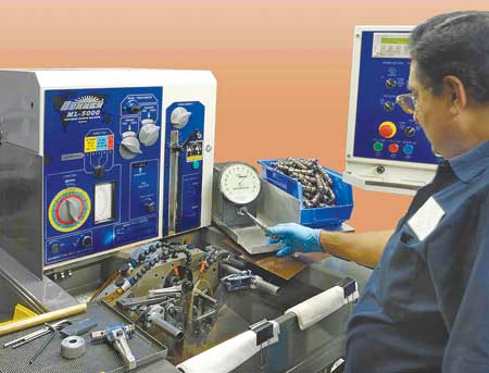
High performance aerospace hydraulic valves can be honed to bore diameter tolerances of 0.00025 mm to 0.0005 mm (0.000010" to 0.000020"). Operator is shown gaging parts after honing.
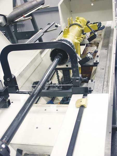
A landing gear housing is set up for honing in horizontal orientation. These parts can also be honed in the vertical position, sometimes considered preferable.
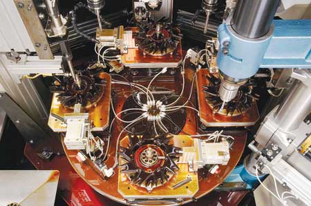
A viewpoint from above the honing machine's rotary indexing table shows machine spindles, tooling, air gaging probes and a final brushing station. The part in the workpiece fixture is a piston pump body.
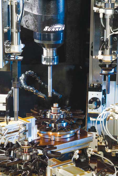
Piston pumps used in hydraulic flight control systems have clearances of 0.005 mm between moving parts, requiring ultra-precise bore size, roundness, straightness, etc. The photo shows piston pump bodies in a multi-spindle Sunnen honing machine equipped with air gaging stations between spindles. This machine can control bore size to within 0.00025 mm (0.000010").
Invented more than 70 years ago to de-glaze cylinder bores in early automobile engines, conventional honing today can meet the most advanced aerospace requirements for ultra-precise machined parts. Computer controls, new tool designs, new abrasives, integrated air-gage part measurement and servo-driven tool feed systems and spindles enable new honing machines to produce part bores with 0.000010" accuracy and crosshatched surface finishes targeted to a very narrow range. Honing can even correct bore geometry distortion from upstream machining processes, welding or heat treating. And while most users want a uniform round shape in a bore, honing can also impart a shape, such as a barrel, in a selected region of a bore if desired.
This new generation of machines is enabling aerospace suppliers to meet a host of challenges for parts that include ram-air turbine components, fuse pins, turbine hubs/discs, landing gears, hydraulic valve sleeves, accumulators and pumps.
The aerospace industry is constantly tightening the requirements for parts to achieve lighter weight and, particularly, greater performance from end products - higher power densities, more precise control, tighter sealing, less hysteresis, noise and vibration. Flight control systems are a good example. The ultra-high performance hydraulic valves in these systems are about 125 to 250 mm (5" to 10") long, with a bore of about 12 mm (0.5") diameter, including numerous lands and crossholes. Honing is used to produce bore diameter tolerances of 0.00025 mm to 0.0005 mm (0.000010" to 0.000020"). In fact, some parts are produced to tolerances beyond the measuring capability of many gages. In addition to sizing and finishing the bore, honing perfects the roundness, straightness and finish of the bore. These valves operate with a clearance of 0.005 mm (0.0002") or less between the valve body and match-ground plunger. The same holds true for the moving parts in the pumps that power these systems. As operating clearances between moving parts shrink, honing can tightly control the bore's surface finish to retain a lubricating film of oil.
Similarly, the bores of hydraulic accumulators are honed to eliminate any surface flaws that could propagate into cracks under stress. The bores of fuse pins, used at the attachment points of engine pylons, are honed to precise size and finish tolerances to ensure they shear under the correct level of stress. Multiple components in ram-air turbines are honed, as are the bolt holes in turbine hubs and discs. The bores of gears used by Airbus, Boeing, Cessna and NASA are honed for similar reasons.
Overlaying the need for a bore's precision size and geometry is the requirement for high process capability, an area where servo-controlled honing shines. With the resolution on the tool-feed systems of today's machines, process variability is small and process capability (Cpk) is quite high.
New Tool-Feed Technology Simplifies Process
Typically, a production honing process is set up to use an abrasive tool with a specific grit size and bond optimized for incoming part conditions. Tool expansion to achieve the desired results and final size is programmed based on rate of time. The tool feed system performs the same way on each cycle, starting with touch-off, sensed through spindle load or the force sensed on the tool feed system. Cycle time is always the same. However, when a batch of parts comes in with a different heat treatment, distortion or a size variation, the operator must intervene because the tool may expand too quickly for part conditions and be damaged. In the opposite case with a softer than normal workpiece, the tool will still expand at its programmed rate, when it might have been able to expand faster to reduce cycle time. Expansion at too slow a rate may also result in glazing of the honing stones, which will not self dress if the cutting force is too low. Typically, the operator must tweak the feedrate periodically to compensate for these variables.
New tool feed technology that servo-controls the force in the tool feed system enables the machine to sense, and compensate for, these variables. The new Controlled-Force feature, which works in concert with the machine's standard rate-feed system, functions like cruise control to maintain the optimum cutting load on the honing abrasive throughout a cycle, irrespective of the incoming part's hardness, geometry or size variation. In effect, the machine can detect what is happening in the bore when the abrasive contacts it, whereas with rate-feed alone, the machine feeds the tool per the program, not according to the real conditions the part is experiencing.
With Controlled-Force honing, the machine still uses a programmed feedrate, which is then increased or decreased to maintain a setpoint for the force load on the tool feed system. If the feed force drops off, the system increases the tool feed rate to compensate - resulting in faster cycle time, as just one example. Feed force is monitored every few milliseconds during the cycle to ensure the tool always feeds at the highest rate possible for part conditions.
In a typical scenario on a small pump bore, the tool expands rapidly at the start of the cycle until the system senses 150 N of force, and then climbs gradually to its 200 N setpoint.
"Controlled-Force honing is ideal for applications using metal-bond abrasives," said a company spokesperson. "In extensive tests with cartridge valve cages, it reduced cycle times by 25% to 50%. In testing with diesel cylinder liners, it cut cycle time 50%.
"Controlled force honing also produces more consistent surface finish results. In one application with hard steel parts, standard rate-feed honing produced Rz values of 2 to 7 µm. With Controlled-Force honing, the process consistently holds Rz between 5 to 6.5µm."
Controlled-Force honing sometimes allows use of harder, more durable abrasive bonds, where softer bonds may have been required in the past. As a result, the part yield for a given set of abrasives increases, while the abrasive cost drops. Likewise, Controlled-Force technology eliminates glazing of the abrasive due to too little cutting force. This ensures a steady, free-cutting, self-dressing condition for maximum metal removal in the shortest possible cycle time, according to Sunnen.
Connecting rods illustrate the advantage in honing parts with varying wall thickness. The con rod has the beam on one side - so the rod is very rigid in this thicker area - and the cap on the other side where wall thickness is considerably thinner. As a result, the bore has a tendency to distort more in the weaker area during honing. "On these workpieces with irregular wall thickness, Controlled-Force ensures the system never overloads the tool and distorts the bore," said the spokesperson.
Rate-feed will still be the exclusive tool feed methodology with certain honing tools that use a full wraparound sleeve of metal-bonded diamond abrasive - rather than segments of abrasive - for full contact with the bore surface. These tools are particularly useful for bridging segmented bores, multiple lands, ports, keyways or crossholes. Controlled-rate feeding provides up to five expansion profiles that can be used during a cycle for rapid part touch, cutting, sizing, finishing and spark-out.
Controlled-Force tool feed gives users a new choice to optimize cycle time, abrasive consumption and labor utilization in a production environment where batches of incoming parts may vary slightly. It is available on new machines or as a retrofit for the Sunnen SV-1000 and SV-500 Series.
Authored by Dennis Westhoff, Business Development Manager
For more information contact:
Sunnen Products Company
7910 Manchester Road
St. Louis, MO 63143
800-325-3670 / 314-781-2100
sales@sunnen.com
www.sunnen.com