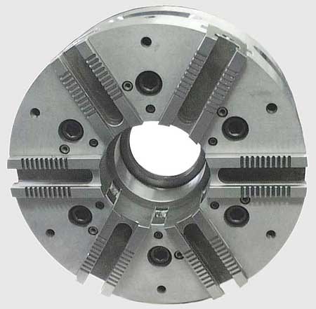
A six-jaw chuck with thru-hole.
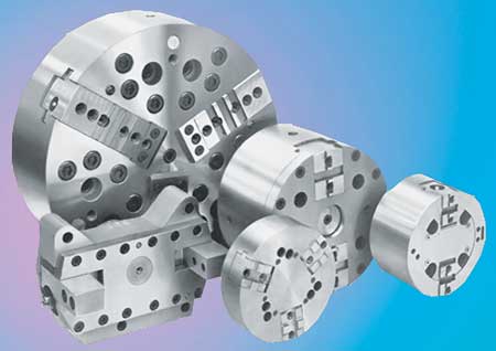
Various types of chucks including two and three jaw chucks.
When processing a part (and to optimize the process), there are a number of considerations in selecting the appropriate chuck. In most cases selecting the workholding is the first consideration in the process.
Initially, one should first look at the workpiece to be held. A round piece of bar stock is the most simple of geometrics to work with. However, not all parts come from bar stock. Some come as castings or forgings with non-uniform shapes. And because of the wide variety of chucks and options available, this is where the selection process requires careful thought and consideration.
The most common chucks are standard two or three jaw chuck and collet chuck. More intricate shaped parts may require an anvil type one jaw chuck or a four or six jaw chuck.
Listed below are the various basic chuck designs and where they are best suited. Each design provides various options, but, for now, here are the basic applications:
- One jaw chuck: used for parts having a qualified side surface as a datum
- Two jaw chuck: used mostly on square shaped parts
- Three jaw chuck: used mostly for round shaped parts
- Four jaw chuck: used to stabilize the grip on square parts
- Six jaw chuck: applied to thin-walled parts requiring wrap-around clamping to avoid distortion
- Collet chuck: used with parts requiring wrap-around clamping while not marking the part, yet still maintaining close concentricity requirements
- Index chuck: used for parts with various centerlines as reference
- Diaphragm chuck: used with parts requiring optimal grip while machining plus critical part tolerance while not allowing distortion and markings.
"It would be great to have all of the above chucks available in your tool room arsenal," said a Royal Machine & Tool Corp. spokesperson. "However, that is never the case."
To select the most appropriate chuck, first review the following categories and determine the best method of chucking based on each of these areas: the workpiece, the machine, the production and the process.
The Workpiece
Finding the best way to hold the part is best determined by the tolerances and operations required to produce the workpiece. It would be ideal to be able to machine the part completely in a single clamping. The objective is always to handle the part as little as possible. In many instances this is possible with the proper choice of chuck. Looking at the variety of chuck styles available will help in making the right decision. Not all parts are symmetrical. Some have a flange or outrigger, which is a concern with both speed and balance. This situation may call for the proper means to counterbalance the part or to reduce the speed of the process.
Sometimes parts are thin-walled and will distort when clamped with a standard three jaw chuck. A collet or diaphragm chuck may be the answer. Or, it may just require a reduced clamping pressure to allow it to secure the part, but not distort the part. In most cases, where distortion occurs, it is because of extreme clamping pressure. The first concern is that the grip pressure be substantial to hold the part in a safe and secure fashion. Once the workpiece is reviewed, move on to determine the machine tool.
The Machine
There are many considerations to review in selecting the machine. Ideally, the part can fit a machine with the right capabilities. However, it may be that one is restricted to a certain machine.
The chuck mounting must be compatible with the machine. What is the machine's speed and horsepower? Is there sufficient RPM to obtain the surface footage required? Does the machine cylinder have the necessary pressure for the chuck and is there adequate cylinder stroke to actuate the chuck? Finally, is there enough swing clearance for the chuck, part and the tooling to process the part? The work envelope of the machine may restrict capabilities.
Modifications may have to be made to the machine if an application calls for special fixturing, such as an index chuck or a chuck with retractable locators. In most cases, when looking at index chucks, they require a separate hydraulic unit, double-acting cylinders, cylinder adapter and tubing in lieu of a standard cylinder and drawbar or drawtube. Therefore, in some cases changes may need to be made to the machine. For high production applications, these types of changes are usually permanent.
The Production
When making a single piece, it is most appropriate to use a manual operated chuck and universal jaws to clamp the part. Cycle time is not an issue because it is only a single workpiece. The part can be pecked-away-at without concern for any load from clamping or tool pressure. Tolerance and finish are wide open. This scenario plays out every day in many small shops.
High volume production of precision parts may require it to run unmanned, with clamp/unclamp detection as well as pressure monitoring and sensing of proper part location. This is only for the chucking phase, and may also require automatic load/unload, automatic tool offsetting and breakage.
The Processing
The process indicates the datums for the dimensions being machined. In turn, this determines how the part is located and gripped. Look at the tools and their tool path to make certain clearances are available. Clearances can be made as long as the integrity in clamping the part is not breached. This also holds true when allowing room for chip evacuation or coolant.
In many cases the part cannot be completely machined in a single clamping. During the finish operation the part may have to be oriented more precisely or in a different fashion. For example, a part may be held in a three jaw chuck for the roughing operations to remove the material with heavy depths of cut. Where roundness or concentricity are vital for the finish operation, a collet chuck may be the best option.
Once the process is determined, the clamping method can be checked for locating the part appropriately and allowing sufficient clearance for the tooling, coolant flow and chip evacuation.
Reviewing each of these four categories should assist in determining the appropriate chuck and top tooling to safely produce a quality part in a timely fashion.
Authored by Bernie McAloon, Sales Manager, Royal Machine & Tool Corp.
For more information contact:
Bernie McAloon, Sales Manager
Royal Machine & Tool Corp.
P.O. Box Y
4 Willow Brook Drive
Berlin, CT 06037
860-828-6555
royal@royalworkholding.com
www.royalworkholding.com