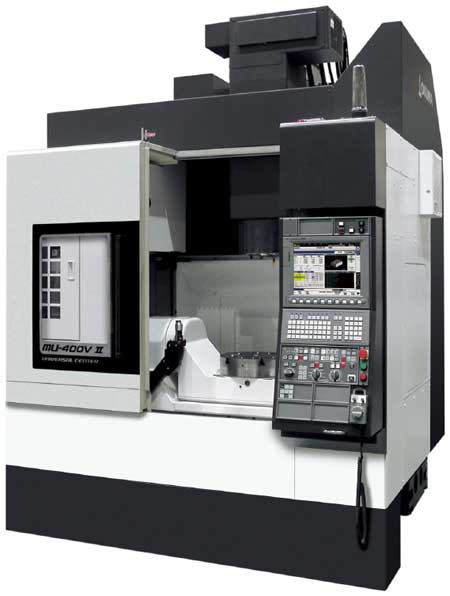
Five-axis machining center MU-400V II. Courtesy of Okuma America.
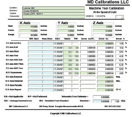
MD Calibrations Volumetric Error Estimator (VEE)
When purchasing a new or used machine, it is imperative to protect the investment in order to obtain positive return on investment. The overall objective is to maintain maximum performance and minimum downtime. MD Calibrations achieves this by applying C4, "."
3D Characterization
"When a machine is delivered and installed, the machine's performance has usually been documented back at the factory or at a previous facility," said Mike Denomme, MD Calibrations, LLC. "The machine is placed on a new foundation in a completely different environment. The machine's performance is entirely different than what it was previously. The geometry (roll, pitch, yaw, squareness and straightness) has changed. Each of these parametric errors has a tolerance assigned to it. Take angular errors roll, pitch and yaw. Say we assign a tolerance of +/- 5 seconds. Say at the factory the X-axis pitch was adjusted to +5 seconds. On the new foundation it is then adjusted to within -5 seconds. This machine is then technically within OEM specifications. Consider what this change has on the machine's performance and what can be done about it - especially when the overall concern is the machine's volumetric performance. Quite often, here at MD Calibrations, we witness situations like this where the machine has been installed and the geometry adjusted. Then, the end user begins the arduous task of debugging the machine's performance problems by trying to manufacture parts. The result is a lot of head scratching and frustration."
Upon completion of an installation, MD Calibrations recommends a full 3D characterization be performed. In compliance with national and international standards, such as ANSI/ASME B5.54, ANSI/ASME B5.57 and ISO-230, this testing is performed after the installation has been completed, all covers and guards have been installed and the machine is ready for production. The machine's geometry is measured and documented in compliance with the standards. Testing must be performed without making any on the fly adjustments to the machine. Any geometry adjustments made during the machine testing may or may not make changes to geometry that has already been documented. The whole idea of a 3D characterization is to document the machine that will be placed into production.
3D characterization of a 5-axis machine consists of the following tests:
- X-axis Roll, Pitch and Yaw
- X-axis Straightness (XY and XZ)
- XY Squareness
- X Positioning
- X Periodic Error
- Y-axis Roll, Pitch and Yaw
- Y-axis Straightness (YZ and YX)
- YZ Squareness
- Y Positioning
- Y Periodic Error
- Z-axis Roll, Pitch and Yaw
- Z-axis Straightness (ZX and ZY)
- ZX Squareness
- Z Positioning
- Z Periodic Error
- A-axis Parallel to Y axis
- A-axis Positioning
- A-axis Periodic Error
- C-axis Parallel to Z axis
- C-axis Squareness to Y axis
- C-axis Positioning
- C-axis Periodic Error.
Upon completion of documenting the machine's parametric errors, MD Calibrations uses its Volumetric Error Estimator (VEE) form to sum the errors and determine the machine's 3D performance using the method of square root sum of the squares. This form is used to clearly document the machine's as-found condition for 3D performance. If all geometry errors documented are within OEM specifications, the team proceeds to the next step. The machine's linear and rotary axis positioning errors are optimized.
Compensation
Today's machine tool controls are equipped with the ability to optimize a machine's linear and rotary positioning. MD Calibrations utilizes the Renishaw XL80 laser system to accurately measure linear positioning. The XL80 laser, in conjunction with the Renishaw RX10 or XR20, is used to measure rotary positioning. The XL80 laser, in conjunction with the XR20 and Renishaw OAR software, is used to measure trunnion axes. "The accuracy of the data acquired by these devices plays a large role in the accuracy of the performance optimization," said Denomme. "Proper compensation is a lot more than just entering correction data into a control. Establishing a proper pitch line for the product or products to be produced on the machine, proper evaluation of the environment, using the proper expansion coefficient and controlling thermal drift play a very big role in obtaining accurate compensation data. If the machine is properly optimized it will operate at peak performance. Upon completion of optimization, the linear and rotary positioning data is then used to replace the as-found data that was originally entered into the VEE form. This way we are able to quantize the improvements made by optimization. We have now established a baseline for future evaluation and calibration of the machine throughout its lifespan."
Calibration
The next step is machine calibration. This consists of running a number of tests on the linear and rotary axes using traceable calibration devices. "During calibration it is important to select a national or international standard that the entire calibration test will be in compliance with," said Denomme. "The calibration equipment must itself be calibrated at the interval recommended by the OEM. At MD Calibrations we use the Renishaw line of machine tool calibration equipment, which includes the XL80 laser, XR20 rotary calibrator and the QC20 telescopic ball bar. We use the ISO-230 standard as our reference for the collection, analysis and display of data. Five bi-directional runs are performed, recording positions at 1/10th of the linear axes and every 15° on rotary axes and 10° on trunnion axes. While ISO-230 is our standard method for calibrations, we can also perform calibrations to ANSI/ASME B5.54, ANSI/ASME B5.57, ISO-10791 and ISO-13041. These standards typically refer back to ISO-230 for the methods of data acquisition and analysis."
According to Denomme, calibration of a 5-axis machine consists of running the following tests as a minimum:
- X-, Y- and Z-axis Linear Positioning
- X, Y and Z Periodic Error
- XY, YZ and ZX Contouring Performance
- A and C Rotary Positioning
- A and C Rotary Periodic Error
- XYZ Laser Diagonal Test (optional and only performed if requested by the customer).
Certification
"While all machine tools should be periodically calibrated, not all machine tools require certification. However, machines that utilize on-machine gauging as part of their quality process should be calibrated and certified at least annually," said Denomme.
For certification, all of the data acquired during calibration is compiled into a report that provides full documentation in accordance with the selected national or international standard. "The standards are very specific as to what needs to be recorded," said Denomme. "This includes data such as the as-found condition, position of the optics and pitch line, expansion coefficient, whether NDE was used, the feed rates applied, dwell time for measurement, type of feedback, position of the environmental sensors, position of axes not under test, offset to tool reference, offset to workpiece reference, test starting and ending temperatures, measurement uncertainty, etc. This information is documented in order to obtain repeatability and reproducibility of the measurement results."
Finally, a calibration certificate is issued. This is a compilation of the data acquired and analyzed and demonstrates equipment traceability to NIST or other national/international laboratory.
According to Denomme, ISO-230 recommends the following machine performance data to be presented with a calibration certification:
- Bi-directional accuracy of positioning of an axis. This is the range derived from the combination of the bi-directional systematic deviations and the estimator for axis repeatability of bi-directional positioning using a coverage factor of 2.
- Unidirectional accuracy of position of an axis. This is the range derived from the combination of the unidirectional systemic deviations and the estimator for axis repeatability of unidirectional positioning using a coverage factor of 2.
- Bi-directional systematic positional deviation of an axis. This is the difference between the algebraic maximum and minimum of the mean unidirectional positional deviations for both approach directions at any position along or around an axis.
- Unidirectional systematic positional deviation of an axis. This is the difference between the algebraic maximum and minimum of the mean unidirectional positional deviations for one approach direction (either positive or negative) at any position along or around an axis.
- Range of the mean bi-directional positional deviation of an axis. This is the difference between bi-directional algebraic maximum and minimum of the mean bi-directional positional deviations at any position along or around the axis.
- Bi-directional repeatability of positioning of an axis. This is the maximum value of the repeatability of any position along or around the axis.
- Unidirectional repeatability of positioning of an axis. This is the maximum value of the repeatability at any position for one approach direction (either positive or negative) along or around the axis.
- Reversal value of an axis. This is the absolute reversal values at all target positions along or around the axis.
- Mean reversal value of an axis. This is the arithmetic mean of the reversal values at all target positions along or around the axis.
For more information contact:
MD Calibrations, LLC
102 Perry Street
Douglas, MA 01516
877-632-2542
www.mdcalibrations.com