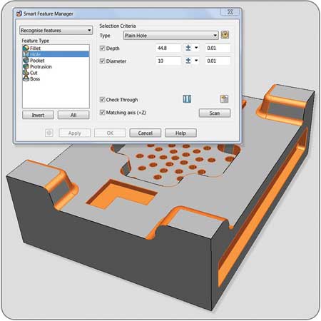
PowerSHAPE's Smart Feature Manager allows users to identify all the features within a solid in a single operation.
The 2014 release of Delcam's PowerSHAPE CAD software offers a range of new functionality for the conversion of product designs into tooling designs. The company reported that the software now provides easy-to-use tools designed to increase productivity through automation and improved workflow.
"By offering a combination of modeling and reverse engineering functionality, PowerSHAPE provides a comprehensive range of design techniques in a single CAD program," said a company spokesperson. "Having all the different technologies in the same package reduces the need to transfer data between multiple programs and so streamlines the whole product development process. At the same time, the combination of quick and easy direct modeling options, together with surface modeling, makes PowerSHAPE the perfect choice for design for manufacture."
The Solid Doctor in PowerSHAPE is designed to provide quick and easy repair of imported data from other CAD systems. For the 2014 release, these capabilities have been enhanced with the addition of the Smart Feature Manager. PowerSHAPE can already recognize a variety of solid features within imported "dumb" geometry, such as fillets, slots, bosses, etc. The Smart Feature Manager allows users to identify all these features within a solid in a single operation and so makes the analysis of the imported data easier and faster.
The software includes a set of filters so that all the features that fulfill specific criteria can be identified within the model. For example, the Smart Feature Manager can find all the holes having the same, specified diameter, or those having radii between two values. Similarly, if a single feature is selected, all similar features can be identified with a single click.
Once the particular group has been isolated, all the features within it can be suppressed or deleted simultaneously. Creating groups of similar features also makes it easier to manage the feature tree.
One common problem for tooling designers is finding fillets that are too small for successful filling of the mold. The Smart Feature Manager can be used to identify all the fillets having radii less than a particular size so that they can be modified to more suitable values.
When creating fillets, two new types of solid fillet have been added to options in PowerSHAPE. Constant-width fillets create a blend based on a nominal radius when the distance between two edges remains fixed. Curvature-continuous fillets create a smooth blend between the selected edges. They have curved cross-sections, with the radius of the curve varying continuously to match the curvature of the underlying faces.
Another common requirement for tooling design is adding draft surfaces and split surfaces to the model. These modifications and similar repetitive tasks have been made simpler through the addition of "Apply" buttons to all the surface-creation dialogs that allow multiple operations or operations on multiple surfaces without leaving the form. Clicking the right mouse button has the same effect as pressing "Apply", which further speeds up repetitive operations.
The core/cavity separation wizard in PowerSHAPE has been rewritten to make it faster and more effective. It divides the solid model into core and cavity pieces that can then be separated dynamically using a simple slider.
Any ambiguous faces can be assigned to the appropriate side, while any regions where slides or lifters might be required can be allocated to a completely new line of draw. If required, individual faces can be split and then attached to the correct part of the tool.
Throughout the process, clear graphical feedback, including undercut shading, highlights any potential molding issues arising from the design so these can be corrected at an early stage in the mold design process.
Another addition is a new "solid extrusion" tool that allows solids to be created from multiple nested curves in a single operation. Any inner curves are extracted automatically from the solids to give hollow shapes. This option can be used for creating embossed text, such as part numbers or product names, and similar complex-shaped features.
For more information contact:
Delcam
877-335-2261
marketing@delcam.com
www.delcam.com