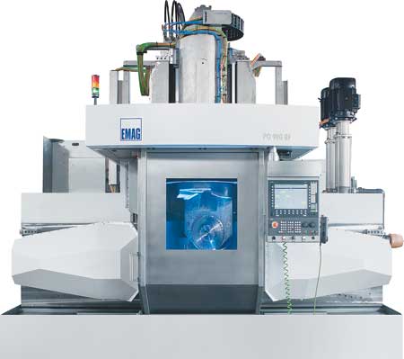
Blisk machining on an EMAG PO 900 BF.
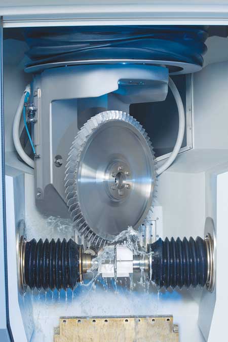
Tooling area of an EMAG PO 900 BF for the machining of blisks using Precise Electro-Chemical Machining (PECM) technology.
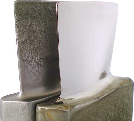
Left: rough-machining, right: finish-machining.
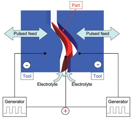
Schematic diagram of a synchronized PECM machining operation.
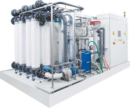
Electrolyte management.
According to a recent survey by Boeing, the number of aircraft deployed worldwide will double within the next 20 years. This will, of course, lead to an enormous increase in the number of aircraft engines required. It is not only the increasing demand for engines that pose new challenges to engine manufacturers, but also ever tightening environmental standards.
Three criteria characterize the demands on aircraft engine production, according to EMAG. Amidst increasing cost pressures and fierce competition, the market calls for engines with significantly improved fuel efficiency. Environmental regulations toughen demands for emission reductions. Additionally, there is a need to reduce purchase and maintenance costs of new aircraft engines.
Fuel consumption and emission levels go hand-in-hand and are, to a large extent, determined by the design of the various compression stages of the engine. Every increase in efficiency brings with it a reduction in fuel consumption and, in turn, CO2 emissions.
An increase in speed leads to an increased compression ratio between the various compression stages and to the desired increase of thermal efficiency. This strategy will, at the same time, bring about a reduction of the required number of blades, which allows for an optimal aerodynamic design of the individual blades. Higher speeds and temperatures exert increasing pressure on the compressor rotor, which must be taken into consideration when opting for an integral design, where the mechanical connection between blade root and disk disappears and the rotor is produced as an integral component (a blisk is a blade integrated disk).
This ensures that the high loads on the blade root are absorbed by the entire disk. It then removes the mechanical connection between the two components and the integral design provides for a mass-reducing construction that offers greater economic viability.
In the past, the choice of material used in such cases fell to nickel-based alloys, since the high operating temperatures in the high-pressure compressor environment had to be taken into account. The effort to satisfy the ever increasing demands for higher temperatures and a reduction in component weight has, for some time, concentrated on the use of titanium alloy replacements. Development in this area has advanced significantly, with materials reaching official safety class 1 approval in the rotating components sector. These new alloys are even more difficult to machine in comparison, so it is imperative to find alternative production processes that satisfy economic and technological requirements for both materials. Thus it is imperative to quickly introduce new processes for the production of those aircraft engines still in the development, especially when one considers the increasing requirement for blisk components over the next few years.
ECM Process
Electro-Chemical Machining (ECM) is the removal of metal through electrolysis. The workpiece is polarized positive (anode) and the tool negative (cathode). The working gap is flushed with a conductive electrolytic solution. The introduction of voltage leads to the molecular erosion of the workpiece material. The material removed, metal hydroxide, is flushed out and separated from the electrolyte by a filtering system. The electrolyte is then reused in the process.
The ECM process is most commonly associated with deburring applications, especially in injection technology, where specially designed tools were used to remove material only at strictly localized points - to remove burrs or for the creation of radii. ECM has also been used to create annular grooves, cavities and other geometries.
Using 2.5D imaging technology and DC generators also allows ECM to be used for the countersinking process. However, either the quality of the image proved mediocre or the development costs for the tools to achieve the desired geometry were too high. But, where the results fulfill the requirement, reproducibility of the process is effective, tool wear is minimal and the hardness of the material has no negative influence on material removal rates. If the machining surface for the cathode is increased, the process does not lengthen the cycle time.
PECM Process
With the subsequent development of the ECM process into Precise Electro-Chemical Machining (PECM) it became possible to increase the accuracy of the geometries and reduce the development costs involved in achieving the required final results.
To achieve precise workpiece geometry, the machining gap is narrowed down considerably. The exchange of electrolytes along with mechanical oscillation in conjunction with feed rate and a pulsed current/voltage source ensures optimal high quality surface finishes.
In the generation of blade geometry and blisks, both sides of the workpiece are machined simultaneously using a synchronized oscillating action.
The monitoring and adjustment of voltage, current and electrolyte flow offers optimal process integrity. Generator technology plays a particularly important role in monitoring working gap, changes in current and fast-action short-circuit shutdowns. Along with an operator-friendly integration of the process parameters, this technology is sure to become the most widely accepted and innovative manufacturing process for the generation of blade and blisk geometry for the future of aircraft engine manufacturing, according to EMAG.
According to EMAG, the major advantages of ECM/PECM are:
- Machining of high-tensile alloys
- Minimal tool wear
- High degree of accuracy
- Excellent surface finishes
- No resulting burrs
- Thermally neutral process has no negative effect on the material
- No recast layer.
An electrolyte management system ensures that the quality (pH and conductance, temperature and purity) of the working medium remains constant at all times. This can be achieved with various filtration techniques (gravity filtration, chambered filter presses, microfiltration), depending on the machining requirement.
Process
For the machining of both single blades and blisks, roughing and finishing operations are recommended. The rough machining process is a pre-contouring operation with open tolerances and feedrates of 2 - 4 mm/min, while leaving enough material for the subsequent finishing process (approx. 0.2 mm). The rough machining operation can be carried out using a variety of tooling strategies economically optimized to suit the relevant geometry. Where the single blade may be machined with a double-sided, synchronized operation, the pre-machining of blisk geometries are best done along the blade's axis. The ECM process has the advantage that tool geometry and suitable scaling of the power supply allow large blades and blisks to be machined at the same feed rates and the same cycle times as smaller single blades.
Machine Concepts
With scalable power supplies and generator technology the whole installation is easily adjusted to suit customer requirements and remain economically viable.
EMAG ECM / PECM technology covers a power range of up to 20,000A DC and a pulse rate of 30,000A. The machine can accommodate workpieces of 900 mm maximum diameter and single blades up to 250 mm in height.
For engine components, EMAG relies on the latest developments of the PO 900 BF machine platform, on which roughing and finish machining operations can be carried out on large single blades and blisks alike. These machines can also be equipped with hydraulic zero-point clamping systems, variable oscillators and automatic tool changers.
For more information contact:
Peter Loetzner
EMAG LLC
38800 Grand River Avenue
Farmington Hills, MI 48335
248-477-7440
info@usa.emag.com
www.emag.com
Southwest
AR
Ken Pope
EMAG LLC
256-642-6842
kpope@emag.com
www.emag.com
TX, OK, LA
Ric Lorilla
EMAG LLC
248-595-1530
rlorilla@emag.com
Southeast
VA, NC, SC, GA, FL
David Fitzgerald
EMAG LLC
248-595-1117
TN, AL, MS
Ken Pope
EMAG LLC
256-642-6842
kpope@emag.com
www.emag.com
Northeast
PA, NY
Kirk Stewart
EMAG LLC
248-996-4703
kstewart@emag.com
ME, NH, VT, MA, RI, CT, NJ, DE, MD
Jonathan Chomicz
EMAG LLC
248-497-8526
jchomicz@emag.com
WV
Ken Pope
EMAG LLC
256-642-6842
kpope@emag.com
www.emag.com
Midwest
IN, OH
Kirk Stewart
EMAG LLC
248-996-4703
kstewart@emag.com
MI
Geoff Fuller
EMAG LLC
248-632-2021
gfuller@emag.com
ND, MN, WI, SD, NE, KS, IA, MO, IL
Bill Konetski
EMAG LLC
612-804-0857
bkonetski@emag.com
KY
Ken Pope
EMAG LLC
256-642-6842
kpope@emag.com
www.emag.com
West
Arnie Sugiyama
Caltec International
19801 Hamilton Ave
Torrance, CA 90502
310-527-4110
arnie@caltecusa.com